
Sensor signals in the form of a 4 to 20mA current loop are commonplace in industrial systems. Devices using this form of signal output are referred to as transmitters. The current loop signal has the advantages of noise immunity, very long cable lengths, and only two wire connectivity.
If all of the factors for a loop transmitter system are not taken into account, the system may not function or have limited functionality. This note describes the how to calculate the system requirements and limitations.
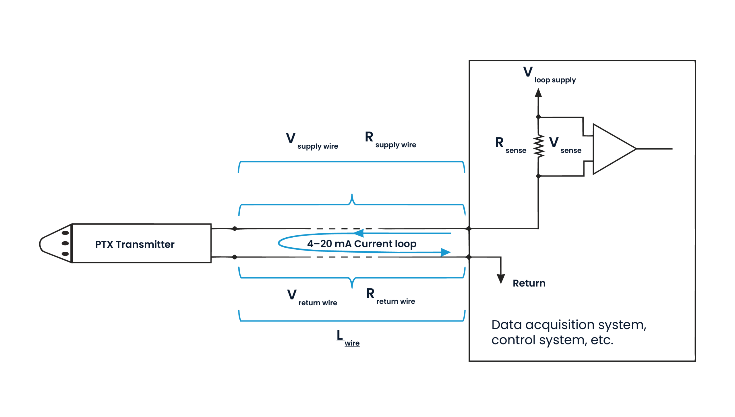
The system of a pressure transmitter and a host system (e.g. data acquisition system, control system, etc.) is modeled below.
Long cable lengths or a low V₍supply₎ voltage can cause the voltage at the transmitter, V₍transmitter₎, to be lower than required for the transmitter to operate. Knowledge of the data acquisition system and its sense resistance and loop supply voltage is imperative. The voltage at the transmitter is:
V₍transmitter₎ = V₍loop supply₎ – V₍sense₎ – V₍supply wire₎ – V₍return wire₎
We assume the supply wire and the return wire are the same length and the same gauge. This makes R₍supply wire₎ = R₍return wire₎ (we can call this R_wire). Being a current loop, they both experience the same current. So by Ohm’s law, V = I × R, they both have the same voltage drop,
V₍supply wire₎ = V₍return wire₎ (we can call this V_wire).
We can simplify the transmitter voltage equation to:
V₍transmitter₎ = V₍loop supply₎ – V₍sense₎ – 2 × V_wire
Again, using Ohm’s law, the voltage drop across a length of wire is directly proportional to current and the resistance. The worst case voltage drop will be when the transmitter output is at its highest, 20 mA. For ease of calculation, we express this in amps, 0.020 A.
The voltage drop across the sense resistor is: V₍sense₎ = 0.020 A × R₍sense₎
The voltage at the transmitter can be calculated by: V₍transmitter₎ = V₍loop supply₎ – (0.020 A × R₍sense₎) – 2 × (0.020 A × R_wire)
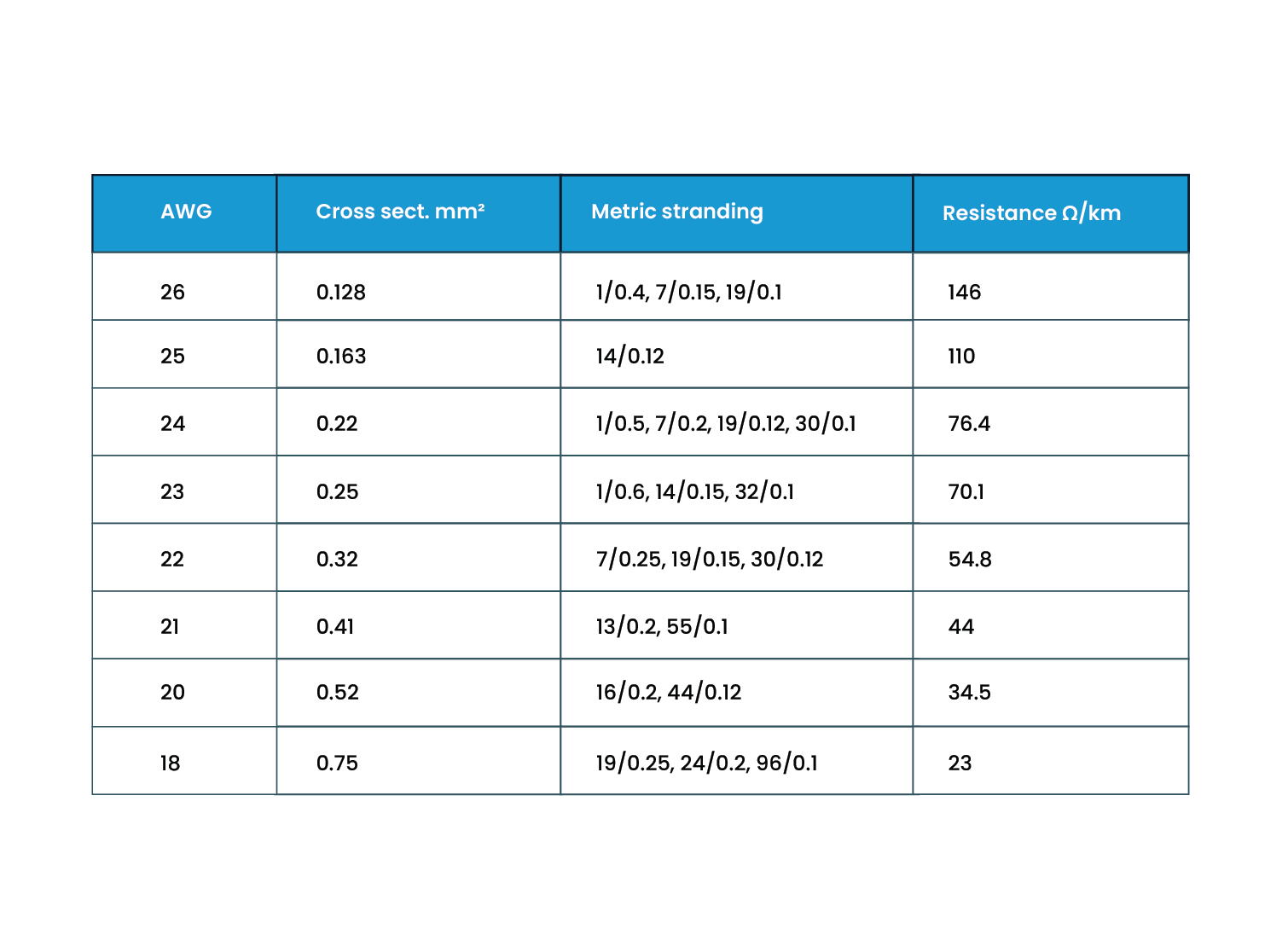
The resistance of the wire will depend on its construction, material, gauge, and length. It is generally expressed as a resistance per unit length, e.g. Ω/ft or Ω/m. For most Druck cabled transmitters, the wire is 24 AWG, made up of seven strands of 0.2 mm tinned copper wire. This has a resistance of 0.0235 Ω/ft or 0.0764 Ω/m.
Historically DAQ or control systems use a sense resistance of 250 Ω. More modern systems use a lower resistance to measure the current, such as 100 Ω. We can plug this into the equation above and simplify:
V₍transmitter₎ = V₍loop supply₎ – (0.020 A × 250 Ω) – 2 × (0.020 A × 0.0235 Ω/ft × L_wire‑ft)
V₍transmitter₎ = V₍loop supply₎ – 5 V – 0.00094 V/ft × L_wire‑ft
(in meters: V₍transmitter₎ = V₍loop supply₎ – 5 V – 0.00306 V/m × L_wire‑m)
For Druck depth transmitters, e.g. PTX1830, the minimum operating voltage is 9 V. This means that the loop supply voltage must be greater than 14 V (9 V + 5 V for the sense resistor) by 0.00094 V/ft × L_wire‑ft.
In other words, for every 1000 ft of cable, V₍loop supply₎ needs to be 0.94 V greater than 14 V.
For a PTX1830 with a loop supply of 12 V, a 250 Ω sense resistor, and no cable, the highest the system could read is 50% FS (12 mA). This is obviously a problem. The V₍loop supply₎ would have to be at least 14 V and that would still not allow for any length of cable.
With a more modern 100 Ω sense resistor and a V₍loop supply₎ of 12 V, it would achieve 100% full scale but there would be a cable length limitation of 532 ft.
For wire other than what is provided with a transmitter, the resistance can be found below.
- Contact Us
- Continue exploring Druck's Technical notes
- Learn more about Druck's market leading pressure sensor range
